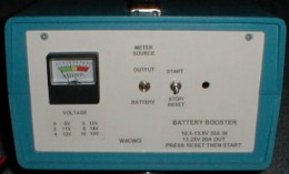
BATTERY BOOSTER |
Boosts 12V Deep Cycle battery to 13.2V regulated over 10.5-13V in. |
DC Power Losses - Part I C. W. Gantt - W4CWG I have noticed at several of our field operations that some HF radios start to act "funny" (reduced output, higher ALC indications, having to turn down the mic gain to avoid splatter) as the day wears on. I think I have traced this to a combination of factors involving the power source. The power supply voltage specs from three HF radios are listed below in the form Nominal(Min-Max). The peak current requirement for all three is approximately 20A. On SSB this current is needed on audio peaks. It is not stated where the voltage measurement is taken (at the source, at the rear panel connector, etc.). I assume it means measured at the power supply end of the factory supplied power cable. Kenwood TS430S: 13.8V (12.0-16.0) Yaesu 757GX: 13.5V (12.0-15.0) ICOM IC746: 13.8V (11.8-15.8) Most AC line operated "12V" DC power supplies put out 13.5 to 13.8V and drop less than a volt under full load, well within the limits. A car battery with the engine running supplies approximately 14.0-15.0V so this falls in the allowed range, too. If you turn the engine off the battery voltage will quickly drop to approximately 12.6V, still in the allowed range. If you are using a deep cycle battery it starts out at approximately 12.6V. If, however, you expect to use the full Amp-Hour (AH) rating (abbreviated as C), you have to use the battery until the voltage drops to approximately 10.5V at a current of C/20 or 5A for the typical 12V deep cycle. This is well below the minimum operating voltage for most radios. In fact at 20A (or C/5) the voltage will drop to 10.5V on peaks long before the battery is fully discharged. There are a number of opportunities for additional voltage drops in the power connection. Here are some measurements I made at a current of 20A using a DC load resistor. Note that if you have a problem the numbers will be higher! � An additional 30A inline safety fuse in the positive battery lead drops 0.38V. This seemed high but another fuse holder dropped 0.5V. � The manufacturer's 20A fuse drops 0.14V. A 30A BUSS auto blade type holder/fuse from Wal-Mart or an auto supply place only drops 0.1V. � An Anderson Power Pole connector (both leads) drops 10- 20mV. � Add anther 0.14V if both leads are fused. � The actual power cable, 10 feet of #12 wire (sum of positive & negative leads) drops 0.65V. � The rear panel transceiver power connector (both leads) drops 0.25V. � The battery drops from 12.6V to 10.5V (2.1V) Add all this up and you get approximately 3.5V if you include the battery. Measurements on a 2M FM rig (Kenwood TM- 261) showed similar drops because even though the current was less, the wire was smaller, both leads were fused, and the connector was smaller. It's no wonder things get "funny" long before a battery is fully discharged! You also get a significant (50% ?) drop in output power. If you want to check out your portable or mobile setup, start by connecting a Digital Volt Meter (DVM) at the radio (straight pins slid carefully into a connector or piercing a wire help) and measure the voltage on receive and at full power. Then start measuring the drop across individual components. A cheap and dirty alternative is on a cool day after a long-winded transmission to quickly feel along the power connections. Heat means loss. I noticed in the latest 73 Magazine a device that connects between the battery and rig and supplies a regulated 13.5V at 23A even as the battery discharges down to 11V. (See http://members.cox.net/w4rry/index.html). How does it do this? I suspect there is a switching power supply inside that supplies 1.0 to 2.5V and adds it in series with the battery. If this device is 70% efficient it would draw an additional 8A (max) on peaks from an 11V battery. So what can you do in lieu of forking out $100? 1. Switch batteries when the voltage drops to the radio's lower voltage limit on peaks. 2. Use a short power cord of #10 wire 3. Use only one fuse for portable operation 4. Check drop across fuses and connectors 5. Connect a 6V battery in series with your 12V and use a regulator to drop the excess voltage What would it take to build a battery voltage booster? An inductor/transformer wound on a torroid core, a power transistor or FET (or a pair), a rectifier, a fair amount of miscellaneous small parts, a controller chip of some sort, and someone who knows more about designing switching power supplies than I do. With luck, most of the hardware could come from an old PC power supply. I plan to dig around for some design info unless a guru steps forward. You will also know what's up if you see me lugging around old PC power supplies at Shelby. More in Part II if I make any progress! |
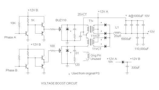
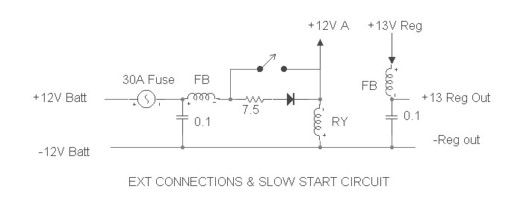
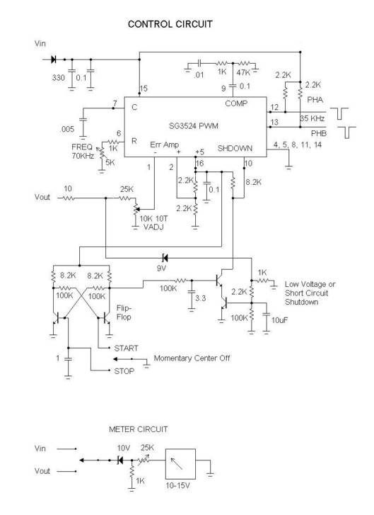
BATTERY BOOSTER C. W. Gantt - W4CWG In my last article I described some problems with using deep cycle batteries for power sources. Primarily the voltage drop of the battery and in the connections causes the radio to transmit erratically before the full capacity of the battery can be used. This article describes a device for boosting and regulating the battery to obtain longer battery life, more power out, and stable transmitter operation. To start this project I scrounged two 250W inoperative computer power supplies from a local computer store's trash bin. The technicians were friendly and curious as to what I wanted the PS for but a few minutes of shoptalk convinced them I was harmless. If you have a choice, older supplies with hefty +5V@25A and +12V@10A outputs are best but take whatever they offer. First, I studied the circuit to see what the original configuration was. Ideally, the transformer will have a primary winding and 24V and 10V center-tapped secondaries feeding rectifiers. It's OK if the two secondary center taps are connected together. Next, I removed the main transformer, filter capacitors, heat sinks, fan, and rectifier diodes. You may be able to use the power transistors but I had better luck with FETs. There are two basic switching regulator configurations that can be used to increase voltage: the "boost" and "transformer". The boost circuit is very simple consisting of just four main components (inductor, power transistor or FET, diode, and filter capacitor) plus a control chip and some glue components. However, early calculations showed that it would draw a peak current of nearly 75A. The transformer version only has to develop the difference voltage to make up for the sagging battery voltage and was calculated to draw a maximum current of approximately 20A. For this reason and the fact that the PC power supply was a transformer configuration, I chose to try the transformer version. Maybe I'll try a "boost" circuit in the future. The new circuit consists of a pair of power FETs driving the 24VCT winding push-pull from 12V. The 10VCT winding feeds two full wave rectifiers in parallel to develop 5V which is added to the original battery voltage. My original PC PS used a choke input on the 5V filter so I did the same. The original transformer primary winding is not used. Warning: the primary has several hundred volts at lethal current during operation! Be Careful! A SG3524N IC ($.70) looks like an ideal control chip but I didn't have one and wanted to try to get something going. So I cobbled together control circuitry consisting of a PIC chip that alternately pulses the FETS (so that they are never both on at the same time) and varies the pulse width to control the output voltage. An op-amp compares the total output voltage to a reference and signals the PIC to raise or lower the output as necessary. The circuit is constructed on perf-board using 5/8" wide strips of .008" copper foil for high current paths. Two strips are used in parallel for the highest current segments. The foil is stood on edge from the board. The control circuitry is on a separate board for convenience during development and debugging and so it can easily be replaced with the SG3524N later. Additional components external to the boards are: 1. A 110,000 MFD 15V filter capacitor to "stiffen" the output and reduce ripple 2. A "soft start" relay to limit inrush current to the above capacitor 3. A meter for monitoring input / output voltage 4. A fan, terminal strip for power, and reset switch for the PIC The resulting circuit seems to work well on the test bench. It can increase a 10.5V battery to 13.4V at 20A out, drawing 32A from the battery. This works out to 80% efficiency with most of the loss apparently in the rectifiers, as they are the only component that gets hot. Of course this is peak output and the overall duty cycle probably brings the average current output requirement down to 5A or so. No-load current is 250mA which will not significantly shorten battery life on receive. I checked for RF noise (always a concern with a switching PS) and couldn't really find any except for a "birdie" at the 20MHz PIC oscillator frequency. The RF transmitter output looked OK on a scope and sounded OK on a second rig. There is approximately 100mV of ripple on receive and 500mV on transmit at full power but it doesn't seem to cause any problems. The ripple is in the 500-2000Hz range and caused by the feedback loop. Hopefully it will go away if I use the SG3524N IC. If you'd like to try building a Battery Booster I'll be glad to provide a schematic, tips, and help getting the smoke out. Switching power supplies are notorious for going up in a flash and puff of smoke if something goes wrong. I used BUZ-110 FETs which are rated at 80A (320A peak), 200W which is almost 10 times the normal peak operating values and did early testing on a 12V, 2A power supply, not a battery. I have not tried shorting the output but expect it would do damage. Also, the circuit doesn't have a crowbar. It peaks out at approximately 18V if the control circuitry is stuck on max with no load. To obtain maximum benefit from the Battery Booster make sure the losses in the power cables from the battery to the Booster and from the Booster to the rig are minimized. Remember the peak current is increased from 20A to 30A so #10 wire is the minimum size from the Booster to the battery. |